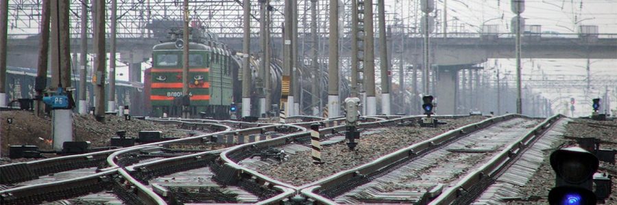
BRC-M2 is intended for centralized traffic control at railway stations and providing remote control of switches, signals and other objects on them, providing the safety of train movement by interlocking switches and signals, automatically controlling the movement of trains, the actions of LTD of the station, the states of railway signaling devices and recording of events (function “black box”).
BRС-M2 is used in the construction of new and reconstruction of existing CTC of any stations, including stations with various types of composite traction system.
The introduction of BRC-M2 allows expanding the functionality opportunities of relay CTC systems and ensuring the required degree of safety and reliability.
The implementation of some functions in the BRC-M2 by means of computer technology makes it possible to reduce the number of relays per switch by 2–2.5 times compared to the CTC of relay type and reduce the area of interlocking room used under the equipment.
Information exchange between system components is based on standard protocols of computing systems and local networks. The use of modern standard computer equipment for input and display of information does not require the manufacture of specialized control devices. (Indication cell and manipulators).
BRC-M2 structure
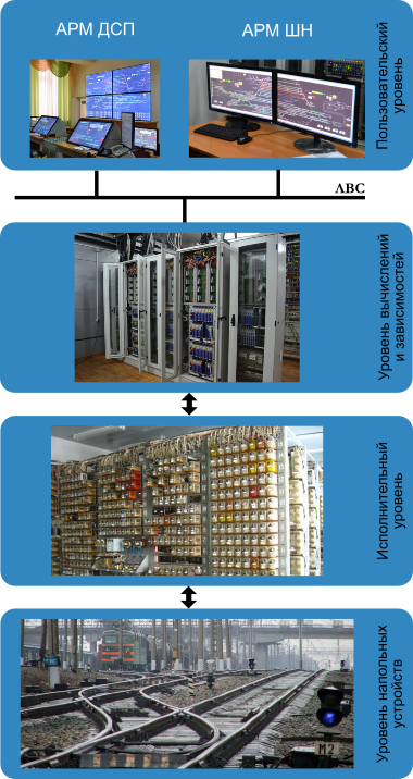
User level
Automated workplaces of the operational and service staff of the station (AWP LTD, AWP signal maintainer) are implemented on redundant industrial computers (“Main” and “Reserved” sets);
Interlocking Calculation level
The complex of technical control equipment (interlocking server), consisting of industrial computers and peripheral devices for input-output information and ensuring the interface of automatic workplaces with relay interlocking schemes. Exchange of information between AWPs and interlocking servers is performed through a local area network;
Executive level
CTC execution schemes provide safety by using the minimum number of safety relays (I class of reliability), as well as rail circuits, interface schemes with running line systems, etc. BRC-M2 is integrated with the executive schemes of any relay СТC (according to generic solutions MRC-9, MRC-13, EC-12, etc.);
Trackside equipment level
Control objects at the station (signals, electric switch mechanism, railroad crossing, track circuits, etc.).
MPO – VV cabinet
MPO-VV cabinet is intended for input-output of discrete information and transfer of TU / TC signals to MPO-C cabinets to interlocking servers of the route set of the relay-processor interlocking system.
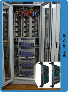
The cabinet includes:
- Input digital signals module MK-TС.56 for 56 inputs (2 groups of 32 and 24 inputs);
- Output digital signals module MK-TУ.32 (32 independent galvanically isolated outputs);
- 19-inch rack is intended to install Input digital signals modules (MK-TS), output digital signals modules (MK-TU) in it, communication modules (MK-ELINK), as well as power supply modules for rack devices;
- Wire board serves to accommodate the terminal boards input / output modules and power terminal wiring modules;
- Fan assembly - a device for cooling modules installed in 19-inch rack with automatic speed control;
- Cabinet 2200х800х600. The cabinet is a metal structure that is installed on the base and contains guides and carriers for installation of equipment.
Server cabinet MPO-C
The server cabinet MPO-C is intended to accommodate the hardware of the server part of the route specefying set of relay- processor interlocking.
All server cabinets MPO-C are made in common industrial design.
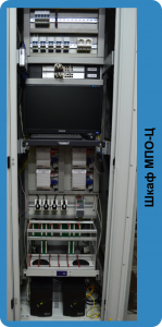
The cabinet is consists of:
- A fanless embedded industrial computer of “Advantech” company. These computers have all-metal aluminum enclosures that protect the computer from dust and dirt, as well as provide their passive cooling. On their base are built interlocking server BRC-M2. A distinctive feature of the PC interlocking server is lack of a hard magnetic storage disk (HDD) - it is replaced by flash memory. This decision provides high reliability and durability of work. In one cabinet of type MPC-C, there are 4 PC - for each set (two in total), two PC on the 1st and 2nd channels, respectively;
- The upper mounting panel is used to accommodate circuit breakers, power supply distribution block and control unit of side walls fan in the cabinet;
- LAN switches is used to integrate devices into an information network using the Ethernet protocol;
- Display (diagonal 22 ") is intended to display information from the PC of the 1st and 2nd channels of the main and rezereved of interlocking sets;
- Keyboard shelf is intended to set the keyboard and the manipulator “mouse”;
- Unifying rack is intended for installation in its the safety modules switching of interlocking sets;
- Fan assembly with automatic speed control is a device for cooling modules installed in the rack;
- KVM switch is a device which is necessary for switching input / output facilities (monitor, keyboard, “mouse”) between the interlocking PCs.
- Uninterruptible power supplies provide power to the PCs when the main power supply is shutdown;
- Cabinet, dimensions: 2200x600x600 mm. A cabinet consists of a metal structure which is installed on the base and contains guides and supporting elements for installation of equipment.
BRC-M2 - PROVIDES:
- centralized traffic at the station;
- automatic notification of workers at the track about approaching a train;
- the implementation of linear functions of centralized dispatching control;
- diagnostics of computing facilities and station equipment;
- implementation of responsible commands, executed without verification of safety conditions and formed by the LTD of the station with certain regulations in case of failure of trackside equipment;
- continuous logging of actions by operational staff and the whole train situation at the station with keeping period minimum 30 days.
BRС-M2 allows providing hardware and software interface with any systems of centralised traffic control and diagnostics and remote monitoring systems.
The RPI BRC-M2, at the request of the customer, may include in its composition a panel or a manipulator panel and a remote display (remote track diagram) as a reserved workplace for the LTD of the station.
In the case implementation of BRC-M2 system with the panel, the following control modes are provided:
- Routing mode of work with AWP LTD simulator. Working with industrial computers AWP LTD simulator of the main set (widescreen touch-screen monitor with a large diagonal and a “mouse”) or a reserved set (controlled by a “mouse”);
- Routing mode from the panel. In this mode, the BRC-M2 performs the functions of a traditional relay routing set from the panel with extended safety checks;
- Auxiliary mode. In this mode, the routing set is disabled. The route is set up by the LTD of the station by manual operation (using the lever on the panel) of the switches along the route. After that, the route can be set up by pressing the signal button of starting the route.
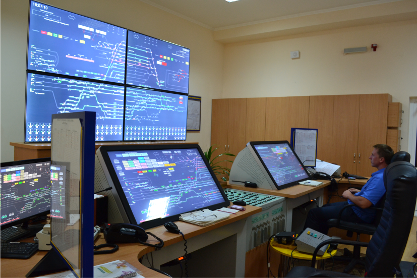
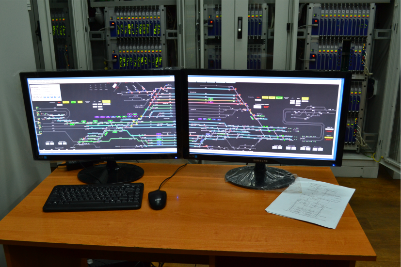
The workplace of the LTD of the station includes a main AWP (touch control panel), a reserved AWP of the station, as well as a station sharing panel.
AWP signal maintainer allows to record the technical condition of the BRC-M2 system in real time and various events.
EXTENDED FUNCTIONAL FEATURES OF THE SYSTEM
- Setting of routes by pressing the buttons start and end of the route on the panel, and an additional pressing of the button of the signal (alternative button), which determines the alternative route in case of setting up of the alternative route;
- Setting of routes with selection of start and end signals of the route at the AWP LTD simulator;
- Contemporaneous preparation and setting of any number of routes of any direction of any type (train or shunting) in the control area of one CTC, excluding the possibility of accumulation of “conflicting” routes;
- Performing extra multiple checking of safety conditions during setting of routes (the main check of safety conditions is performed by relay executive group schemes). If the case of providing safety conditions, the forming of control commands is performed, otherwise, the commands to set routes up are prohibited by the issuance of an appropriate message;
- Perform the cancellation of train and shunting routes with the necessary time delay with the ability of grouping routes of the same type;
- Individual switch operation from the AWP LTD simulator controlling of the freeness of the appropriate switch section;
- Fencing tracks at the request of maintenance depot PTO;
- Changing clear aspect of the signal to the stop one without cancelling the route;
- Set again clear aspect of signal that leads to a locked route;
- Give arrival-signal and give permission (only with SBS);;
- Locating / removing signs of rail boots, railcars on tracks;
- Block / unblock the switch directions;
- Block / unblock of signals, sections;
- The possibility of making text messages by LTD of the station as reminders for element of the station layout (switches, track circuits, signals), which are shown in the AWP LTD simulator when a route is being set (“working people” or “speed limit”, etc.);
- The possibility of banning on the setting of a route through a switch whether completely or only one of its directions;
- Signal maintainer’s possibility of making messages for low-using track circuits for LTD;
- Monitoring of short-term loss of the shunt, short-term of losing control of the switch directions
- Perform diagnosis of BRC-M2;
- Archiving the state of control and monitoring facilities, the technical condition of the BRC-M2 with a storage time of at least 30 days;
- Recording events of maintainers and dispatcher staff with a storing period of at least 30 days;
- The possibility of interacting with the upper level systems (DCS, ACS).
Economic efficiency of BRC-M2
- reduction of equipment compared to relay CTC and reduction of the area of the service and technical facilities of the CTC tower which is used for the equipment;
- reduction of the cost of capital construction, installation and maintenance of the CTC tower equipment through the integration of related signaling systems;
- using of standard input devices and displays for computer equipment does not require specialized manufacturing control board and manipulators;
- the system implements all the functional advantages of modern interlocking, with the performance of functions providing traffic safety of operation is assigned to the minimum number of relays of I class of reliability (safety relays);
- BRC-M2 system is unified for use at all small, medium and large stations of (junctions and rail junctions) with train and shunting movements of mainline and industrial railway transport.

