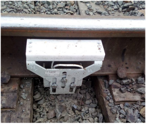
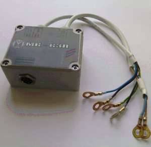
D-KZP2
Two-side occupancy control sensor
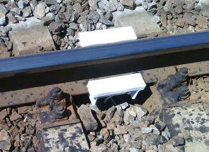
D-KZP
Track occupancy control sensor
Specifications:
- Trackside equipment in a track box or cable box;
- Reverse axle counting;
- Supply voltage from AC or DC source 100-230 V;
- Keeping working of a axle counting in case of failure of one sensitive element of the sensor;
- Transition to the safety prefailed state in case of a malfunction or violation of the sensor mounting;
- Monitoring the presence of a wheel above the sensor;
- Memorizing of the last fixed axle speed;
- Built-in algorithms for self-diagnosis and testing a sensor;
- Power consumption no more than 5 W;
- Protection degree IP66.
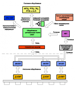
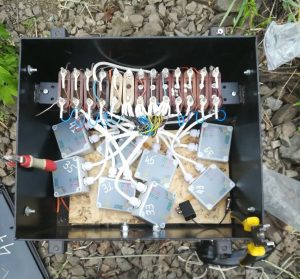
Up to 10 sensors are combined in one beam of controllers MK KZP. To connect a single beam, 4 cable cores are required: 2 power cores and 2 wires of the information communication line.
The two-wire connection of sensors to MK-KZP corresponds to the connection of an existing cable of rail chains and does not require laying a new cable during reconstruction of rail chains.
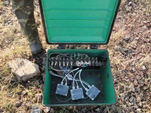
On the field, MK-KZP controllers are located in UPM intermediate couplings, RM branching couplings or traveling, switch or transformer boxes near sensors at a distance of up to 200 meters by cable.
In one UPM coupling, two MK-KZP controllers can be placed.
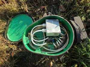
Up to 10 MK-KZP can be placed in one travel box.
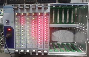
KO-KZP
19 ”CONNECTING RACKS FOR OMTS MODULES
Specifications:
- One racks of OMTS equipment ensures the placement of MK-CP-KZP8 modules for monitoring up to 80 track sections in a single-channel design;
- One cassette of OMTS equipment provides the placement of MK-CP-KZP4 modules for monitoring up to 40 track sections in two-channel design;
- One cabinet of OMTS equipment provides control of up to 320 track sections in single-channel execution and 160 in two-channel;
- There are two versions:
- KO-KZP3M for 3 places MK-CP-KZP
- KO-KZP for 10 seats MK-CP-KZP
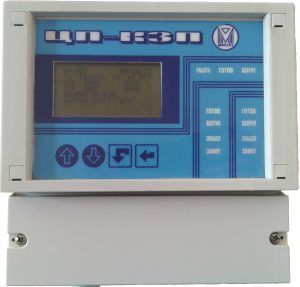
CP-KZP2
Central module of monitoring occuped track for 2 sections
Specifications:
- Number of simultaneously monitored sites 2. For each site, up to 8 input and up to 8 output counting points;
- Power consumption no more than 5 watts;
- Number of inputs –2 galvanically isolated CAN ports. One USB port for communication with a computer. One power input of external relay control circuits +24 V;
- Number of outputs –2 galvanically isolated control outputs of the relay НМШ +24 V 30 mA with protection against short circuit and overvoltage;
- Supply voltage from an alternating current source 130-230 V;
- There is an LED indication of the status of the CPU-KZP2U “Work”, “Ready”, “Alarm”. LED indication of the status of each section “Ready”, “Alarm”, “Free”, “Busy”. Status display on LCD.
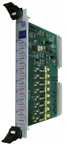
MK-CP-KZP8
Central module of monitoring occuped track for 8 sections
Specifications:
- The number of simultaneously monitored track sections 8. For each section, up to 8 input and up to 8 output counting control points;
- Number of outputs - 8 galvanically isolated control outputs of the relay NMSh +24 V 30 mA with protection against short circuit and overvoltage;
- Number of inputs - 4 galvanically isolated CAN ports. One power input of external relay control circuits +24 V;
- Power consumption of the digital part is not more than 4 watts. The power consumption of one relay control channel is not more than 1.7 watts;
- LED indication of a state of the MK-CP-KZP8 “Work”, ”Ready”, “Failure”. LED indication of the states of each track section “Occupied”, “Free”, “Failure”;
- Protection from impulsive noise and overvoltage;
- Tinctures are stored in microchips of external flash memory, replacement of modules without tincture.
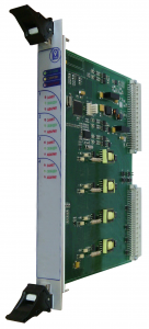
MK-CP-KZP4
Central module of monitoring occuped track for four sections
Specifications:
- The number of simultaneously monitored track sections 4. For each section, up to 8 input and up to 8 output counting control points;
- Number of outputs - 4 galvanically isolated control outputs of the relay NMSh +24 V 55 mA, with protection against short circuit and overvoltage;
- Number of inputs - 4 galvanically isolated CAN ports. 4 power inputs of external control circuits of the relay +24 V. 4 inputs for auxiliary releasing of controlled sections;
- Power consumption of the digital part is not more than 4 watts. Power consumption of one relay control channel is not more than 1.7 W;
- LED indication of a state of the MK-CP-KZP4 “Work”, ”Ready”, “Failure”. LED indication of the states of each track section “Occupied”, “Free”, “Failure”;
- Protection from impulsive noise and overvoltage;
- Tinctures are stored in microchips of external flash memory, replacement of modules without tincture;
- Cascading in a 2 out of 2 scheme to ensure the safety of critical applications.
POWER SUPPLY BP-KZP-2F
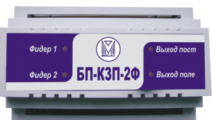
Specifications:
- Provides power to the OMTS devices from two feeders and filtering power supply noise;
- Number of inputs - 2, number of outputs - 2;
- An LED indication of the presence of input and output voltages is provided;
- DIN rail mount.
Microprocessor retransmit line omts RTL-OMTS-CAN
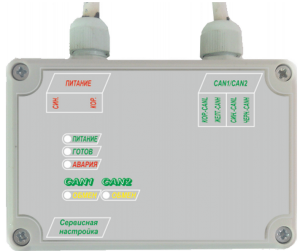
Specifications:
- It is used to increase the equivalent length of the communication line and is set for lines more than 1.5 km;
- Outdoor placement in a travel box or box;
- Supply voltage from an alternating current source of 100-230 V. Power consumption no more than 5 W;
- Number of communication lines: 2 galvanically isolated CAN lines;
- There is a LED indication of the presence of exchange on communication lines, accident, availability.
MK-KPI-CAN/ETHERNET
Microprocessor communication controller
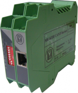
Specifications:
- Designed to convert the CAN network interface to the Ethernet network interface and vice versa;
- 1 port Ethernet port 10 \ 100BASE-TX;
- 2 galvanically isolated CAN ports 1Mbit CAN 2.0;
- 1 RS485 port;
- Connect up to 10 network clients;
- There is a LED indication of the presence of exchange on all communication lines, the state of readiness and accident;
- Built-in WEB service for monitoring, statistics and parameter settings.
BZL-CAN
CAN line protection unit
Specifications:
- Protects CAN communication lines from electrical noise, overvoltage, and lightning discharges;
- The number of inputs - CAN lines -1, the number of outputs of CAN lines-1;
- DIN rail mount.
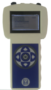
PKD-KZP
Device for control and diagnostics d-kzp, mk-kzp
Specifications:
- Allows you to configure and diagnose MK-KZP and D-KZP;
- Automatically detects CAN bus speed, scans the bus, detects the presence of MK-KZP;
- Analysis and analysis of basic and diagnostic information MK-KZP from the CAN line with an indication of all operating parameters;
- Built-in configuration tools MK-KZP allow you to change the device number and all its operating parameters;
- Connecting and powering the D-KZP from the battery built into the device, checking and displaying all operating parameters;
- Galvanic isolation of the CAN bus;
- Automatic protection of internal circuits against high voltage during CAN bus diagnostics up to 350V;
- Equipped with a built-in battery, battery use from 10 to 24 hours;
- Charge the internal battery from the AC adapter or USB 5V 2A charger;
- 3 '' working screen;
- It is completed with a portable bag for the device and all connection cords;
- Overall dimensions 220x110x50 mm.
MM-OMTS
Monitoring and archiving module
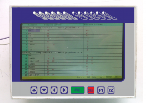
Designed for monitoring and archiving the state of the OMTS.
Specifications:
- View the status of monitored track sections in real time;
- Indication of all operating parameters of MK-KZP, MK-CPU-KZP;
- Monitoring the status of MK-KZP of each site, with the issuance of messages about the refusal;
- Archiving and saving on a memory card 4- 64 GB;
- TFT 7 '' working screen;
- 2 CAN ports 1Mbit CAN 2.0;
- 1 RS485 / 422 port;
- 1 Ethernet port 10 \ 100BASE-TX;
- Powered by a 9–36 V DC voltage source or built-in battery;
- Ability to read the archive via USB or Ethernet;
- There is a LED indication of the presence of exchange on all communication lines, the state of readiness and accident;
- Built-in WEB service for monitoring, statistics and parameter settings;
- Overall dimensions 200x150x70 mm.
AWP for monitoring and archive of axes account AWP-OMTS
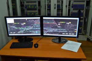
AWP allows you to record the archive, view the current status and the archive of the status of all OMTS devices and train conditions at the station.
Displaying the current state of sensors on the station plan and diagnostic information, pre-failure conditions in real time allows you to quickly eliminate possible damage and increases the availability of the system.
With the help of AWP-OMTS, it is possible to perform artificial release of sections without individual IO buttons on the remote.
ECONOMIC EFFICIENCY OF USING THE SYSTEM
- the system works in any (close to zero) resistance of track ballast, which let significantly reduce the maintaining cost the track and isolated rail joints;
- reducing the cost of equipment sections compared to traditional rail circuits (eliminates the use of expensive copper-containing equipment rail circuits);
- reducing of operating costs, including due to the failure of external relays requiring periodic maintenance in the maintain once;
- increase of an operating availability by diagnosing of potential failures;
- significant cost savings when replacing traditional rail chains due to compatibility with the cable network of rail chains and the lack of the need for new cables and earthwork.