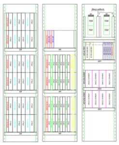
An example of layout of cabinets of generators and receivers of a TRC, coding
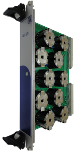
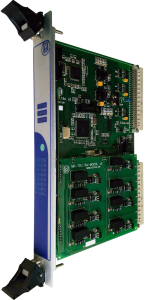
MK-GFPU.6
Six-channel tone frequency track circuits generator
Specifications:
- Power supply voltage - 24V DC
- Dual-channel safety architecture
- Isolation between the channels and between the control electronics and the output of 3kV
- It works through a passive track filter FPU.3.420- FPU3.780 that allows you to get a classic load curve when a train ocupies a track circuit, and also provides generator survivability
- Continuous measuring of the output signal parameters to detect emergency operation and protective shutdown
- The built-in mechanical complete disconnect relay allows you to reliably disconnect the generator when an emergency operation is detected from the track circuit, and also allows for hot standby
MK-PTRC.10
Group receiver tone frequency track circuits
Specifications:
- Dual-channel safety architecture with hardware comparison unit
- Monitors up to 10 receiver ends of AFTC
- Information on all channels passes through the safety hardware “AND”-unit
- The operation algorithm is completely analogous to the actions of an analog receiver, it takes into account both the amplitude and modulation depth of the input signal
- It passes information about the input voltage, modulation depth hardware errors
- Settings are stored in external flash memory chips on each channel, before starting the configuration are compared
- Works together with track filters of type FP.5.420-FP.5.780
FPU.3.420-FPU.3.780
Track filter for tone frequency track circuits generator
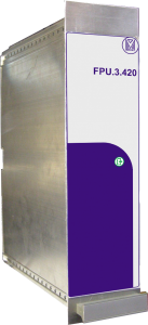
Specifications:
- One link passive output track filter for each channel
- Provides normalized output impedance at natural frequency and low impedance at other frequencies
- No recalculation of normals (requirements) required
- A failure of any filter element is determined with the transition to a protective generator failure
- Provides additional galvanic isolation and generator protection
- Increases system survivability
- Used together with a module MK-GP.6
FP.5.420-FP.5.780
Track filter for tone frequency track circuits receiver
Specifications:
- 5-channel two-link passive input line filter
- Provides normalized input impedance at natural frequency and low resistance at other frequencies;
- No recalculation of normals (requirements) required;
- A failure of any filter element is determined with the transition to the protective failure of the track receiver;
- Provides passing signal ALS, ARS and other frequencies of the AFTC
GFPU.3.420-780
Tone frequency signals generator
Specifications:
- Three independent generating outputs
- Built-in galvanically isolated DC/DC power supply
- Built-in passive track filters allow you to get a classic load curve when a train occupies a track circuit, and also provides generator survivability;
- Two-channel architecture
- Isolation between channels and also between control electronics and 3kV output
- Continuous measuring of the output signal parameters to detect emergency operation and protective shutdown
- The built-in mechanical complete disconnect relay allows you to reliably disconnect the generator when an emergency operation is detected from the track circuit, and also allows for warm standby
- Settings are stored in external flash memory chips on each channel, before starting the configuration are compared
PTRC.5.420-780.RO
Group receiver tone frequency track circuits
Specifications:
- Controls 5 receiver ends of the AFTC
- Built-in two-link passive input track filter per each channel
- Provides a normalized input impedance at its own frequency and low resistance at other frequencies to pass the signal current of ALS, ARS, AFTC
- No recalculation of normals (requirements) is required
- The failure of any filter element is determined with the transition to the protective failure of the receiver
- Built-in galvanically isolated DC/DC power supply
- Dual-channel safety architecture on signal processors with hardware comparison unit
- Information on all channels passes through the safety hardware “AND”-unit
- The operation algorithm is completely analogous to the actions of an analog receiver, it takes into account both the amplitude and modulation depth of the input signal
- It passes information about the input voltage, modulation depth, hardware errors
- Settings are stored in external flash memory chips, before starting the configuration are compared
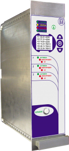
MK-GALS.2.120.MS24/MK-GALS.2.120.MS220
MK-GALS.1.250.MS220
Track circuits code generator with two channels
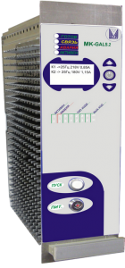
Specifications:
- Two independent channels for signal generation with power up to120W per channel or modification with 1 channel up to 250W
- Signal generation at frequencies of 25, 50 and 75 Hz of a required amplitude and duration
- Provision the synchronization of codes of all generators at a station and a running line
- Power supply voltage - 24V DC or 220 AC
- Dual-channel safety architecture
- Implemented the ability of warm backup generators
- Isolation between the channels and between the control electronics and the output of 3kV
- In each channel, self-diagnosis of internal and output circuits
- Indication of the output signal on the LCD display
- Settings are stored in external flash memory chips on each channel, before starting the configuration are compared
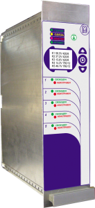
MK-GALS.8
Track circuits code generator with eight channels
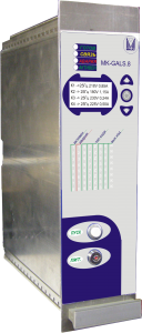
Specifications:
- Switching signal to 220V to 5A on each channel
- Providing the formation of signals with time parameters KPT-5 and KPT-7
- Provision the synchronization of codes of all generators at a station and a running line
- Power supply voltage - 24V DC
- Dual-channel safety architecture
- Implemented the ability of warm backup generators
- Isolation between the channels and between the control electronics and the output of 3kV
- The output of the generator is connected through solid-state relays with a safety “AND”-unit in its input
- In each channel, the measuring of the output voltage and output current
- Indication of the parameters of the output signal on the LCD display
- Settings are stored in external flash memory chips on each channel, before starting the configuration are compared
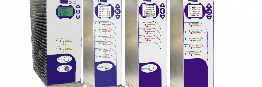
MK-GARS24.2
Automatic speed control signals generator with two channels
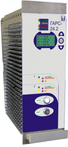
Specifications:
- Providing the formation of automatic speed control signals with frequencies 75-325 Hz
- Providing two outputs with voltage up to 90V and up to 100W per output
- Power supply voltage - 24V DC
- Dual-channel safety architecture
- Possibility of forming a two-frequency signal
- Implemented the ability of warm backup generators
- Repeats the load curve of an analog generator with a filter; when a train occupies a track circuit. It switches to the current stabilization mode (reducing the output voltage)
- Indication of the output signal on the LCD display
- Settings are stored in external flash memory chips on each channel, before starting the configuration are compared
MK-TOS.32.6
Safety input module
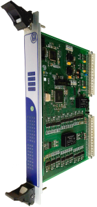
Specifications:
- Safety input of relay status
- Two groups of 16 control inputs each
- Principle of monitoring all three contacts of a relay contact group
- Dual channel safety architecture
- 6 CAN communication lines - 3 per CPU
- Direct independent communication with each operating controller;
- Galvanically isolated test code generator and galvanically isolated code reading to determine relay status
MK-TOU.16.6
Safety output module
Specifications:
- Safety switching on of 16 load channels (relays, etc.) with voltage 24V and current up to 42mA (1 W)
- Each channel is galvanically isolated from power and from each other
- Short circuit detection, load break, command execution control
- Monitoring the availability of output voltage
- Output current control
- Dual-channel safety architecture
- 6 CAN communication lines - 3 per CPU
- Direct independent communication with each operating controller
- Majorization of received commands before execution
- Unstabilized (“dirty”) 24V power supply can be used to control external relays