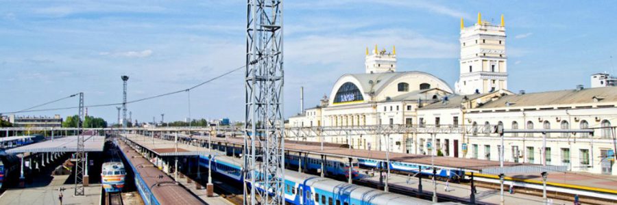
Microprocessor interlocking MIS-MISAT is designed for centralized traffic control in railway stations and on the implementation of their remote control by arrows, signals and other objects, train safety by mutual circuit switches and signals and automatically controlling the movement of trains, the actions of station dispatcher (operator ), the state of devices of railway automation and writting an events archive ("black box");
MIS is intended for the design of new and reconstruction of existing electric interloking (EI) all stations.
Implementation of MIS allows to extend the functionality of relay systems EI in providing the required degree of safety and reliability.
Compared to the relay interlocking of the system through the use of the MIS microprocessor technology offers several new features:
- automatic logging of personnel action, the system and devices (function "black box");
- archiving and database maintenance for the formation of various certificates and reports on the work performed;
- archiving, viewing and statistical processing of information about failures in the devices of EI;
- diagnostics system MIS;
- control and archiving of current in motor control circuits of an electric switch;
- monitoring and archiving of the lamp voltage of rail traffic lights;
- control and archiving of the voltages of the supply panels;
- prompt submission of reference data and data of technical and administrative act of the station;
- automation of management by forming routing tasks for the coming period;
- support for operational staff in non-staff situations (with the exception of incorrect action mode prompt);
- the possibility of withdrawal of the monitors AWS additional information;
- conducting technical diagnostics and monitoring devices pre-failure states;
- EI pairing with a top-level automation, ensuring coordination with the system of supervisory control and remote supervisory control, alarm of railroad workers systems, etc.
The system MIS most of the functions of recruitment and setting of routes are implemented on the basis of small-sized highly reliable micro-processor hardware, in comparison with relay systems allows considerable, but reduce the number of failures by reducing the number of relays and reduce the area of the premises relay.
All interlocking implemented on the basis of microprocessor equipment.
MIS is equipped with means of internal (self) diagnosis, which allows you to manifest "failure to warn" state or failure of components the MIS. Upon detection of a system failure causes MIS outputs object controllers and circuits connected to them in a safe condition.
Outdoor equipment MIS includes standard signaling device (arrows, railway lights, level crossing equipment, etc..).
System MIS-MISAT provides dual control arrows control arrows cleaning, brake control stops, guard convoys on the roads, warning rairoad workers, linking systems HCPS (highway crossing protection system), ASS (automatic switching system) and all types of ABSS (automatic block signal system).
MIS is a modern alternative to the railways operated relay system of EI, provides a significant increase in safety and reliability of traffic control at railway stations.
MIS-MISAT can be used without cascading to build plants with capacity:
- The number of switches to …………............... 256 pcs;
- The number of rail traffic lights to ………...... 512 pcs;
- The number of track circuits to …………........ 1024 pcs.
MIS-MISAT is not inferior in performance to any known analogs, and many of the parameters exceeds them.
Features of the MIS:
- completely non-contact interface with actuators without relay. All interlocking of program implemented in the master controller;
- protected against switching and lightning surges;
- MIS has a high level of safety that meets the requirements of the standard of Ukraine DSTU 4178, and the requirements of international standard IEC 62425 (SIL level 4);
- integrated in the control system of the MIS nearby running lines, crossings and other objects RAT;
- the ability to use of existing track circuits, switches and rail traffic lights;
- replacement of a spare module does not require any action on the programming or adjustment;
- the ability to change the configuration of the control software without the participation of specialists of "R&D Co. KS-MISAT" using special CAD supplied with customer training and certification.
The MIS-MISAT system consists of the:
- cabinets of control with microprocessor system equipment;
- input modules;
- outnput modules;
- item’s controllers;
- CCS’s controllers;
- TRC’s controllers;
- power supply modules;
- two bundles of the control system of the MIS;
- server TDS;
- workstation SDO;
- workstation MIS-Stuff;
- rack power;
- relay circuits linking with the relay system RAT;
- cross equipment with the elements of lightning protection;
- outdoor signaling devices.
Information about the state of the objects come from the input modules, track receivers mall, object controllers, switches and traffic lights on the link in the CAN MIS bundles dependency and to the server TDS.
Commands are sent on the same link from the bundles to the object dependencies MIS switches and traffic controllers, controller CCS, as well as to the output modules, providing switching relay circuits linking.
Bundles of dependency analysis is carried out MIS commands coming from the workstation SDO, in the case of compliance with safety messages on the command generates object controllers, and the opening of the respective outputs of the output modules.
Server TDS collects data from objects of control, analyzes the correct operation of the MIS as a whole, maintains control of the optimal parameters controlled by the currents and voltages, the parameters of the transfer of information along the lines of communications, and maintains an archive of all the conditions and parameters of state control objects. Based on available data defines pre-failure device status signaling and generates the appropriate messages to the staff. The computer also provides an archive at any time, and settings for all the states of control objects.
All electronic equipment, UPS and industrial computers placed in special dust and damp proof control cabinets (IP40).
Workstation SDO consists of an industrial PC, keyboard, manipulator "mouse" and up to two monitors to display more detailed information for the operator. Chipboard using the manipulator "mouse" to manage the switches and traffic lights on the workstation monitor. To ensure higher reliability Workstation SDO incorporates a backup computer.
Workstation consists of electromechanical signaling industrial PC, keyboard, manipulator "mouse" and a monitor that displays the information required by operators. Electrician signaling via the manipulator "mouse" controls the Workstation.
MIS structure consists of three levels:
Custom Level. At this level, there is an interaction with the operating nym and support staff, the exchange of data with top-level automation. Here are located:
- workplace SDO. In the workplace station duty officer (SDO) include: Automated Workstation (AWS) SDO (industrial computers, two widescreen monitors, the manipulator "mouse" and a keyboard), a special computer desk, chair;
- workplace AWS MIS-Stuff. The workstation includes electromechanical signaling: AWS MIS-Stuff (industrial computers, two widescreen monitors, manipulyator "mouse", a keyboard), a special computer desk, chair;
- modems for data exchange with higher-level systems of control and traffic management.
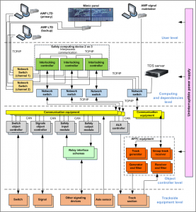
Block diagram of the "MIS-MISAT"
The level of computing and dependencies. At this level there is the collection, analysis, processing, issuing control commands and data archiving, came from the I/O modules, object controllers arrows traffic controller CCS (continuous cab signalling), computer user level. Processing is performed on the relationships defined at the design stage of EI. At this level are placed:
- two interlocking bundles, each dependency set consists of 2 controllers dependencies centralization MK-Z.MPC - 1- and 2-nd channels. This structure placement controllers needed to implement the structure of work "2 to 2", which means:
- at a time can manipulate objects MIS only one set of dependencies, operating on a "2 of 2". Work set on a "2 of 2" has the added benefit in terms of security;
- 2nd set of working in the "hot" re-reserves with respect to the first set of the scheme "2 of 2", but without MIS facility management;
- Safe switching module communication lines interlocking bundles MK-SSW.CAN. The module is designed for safe switching instruction stream on the object controllers (flow direction - "object in the controllers") between the sets of dependencies. Module MK-SSW.CAN also reserved another module MK-SSW.CAN (in "hot" standby).
- Server TDS. Placed in the cabinet layout type MPO-TDS and is an industrial computer, monitor, arm "Mouse" keyboard. RTD server is archiving the situation on the train station, actions by operational personnel and the provision of Technical diagnostics and statistics functions of the station’s client Server TDS – AWS MIS-Stuff workstation at the user level.
Executive level. At this level, object controllers placed arrows, traffic lights, CCS controller, I / O modules, modules, track circuits, relay circuits linkages with systems RAT neighboring stations, playout and other objects RAT relay performance. At the executive level, provides direct supervision and control outdoor objects.
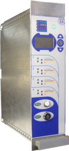
- The switch controller MK-OKST. Designed to control a single or a double switch. Connection to a switch gear typical 5-wire, relay systems used in the EI. Thus, the reduced construction time in the reconstruction of EI (used already laid cable). Performance 6U, installed in 19 "racks.
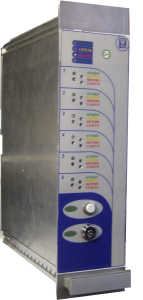
- The object railway light controller MK-OKS. It is intended for management and a control light(s). Connection to a railway light types used in relay systems EI. Thus, the reduced construction time in the reconstruction of EI (used already laid cable). One module MK-OKS can manage more than one railway light, because it has the ability to independently control 6 railway lights bulbs. Performance 6U, installed in 19 "racks.
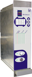
- CCS Controller MK-GALS.8. Designed to continuous cab signalling codes in the rail line. One controller can output a signal coding 8 connection points. Performance 6U, installed in 19 "racks. The controller provides smooth encoding CCS for which switching is made when no current between the sine half-wave. This reduces the noise level that guarantees reliable operation tion of modules and blocks in a tough electromagnetic environment.
- Group track TRC receiver MK-PTRC.10. Modules MK-PTRC.10 together with blocks of active filters MK-FP.5 provide reception of amplitude-modulated signal tone track circuits operating in the frequency range of track circuits TRC3.
- Track generators TRC MK-GP.4. For the formation of the amplitude modulated signal with frequency modulation of 8 or 12 Hz with a fixed sinusoidal carrier frequencies in the range from 420 to 780 Hz as part of equipment control tone track circuits.
- Power's equipment microprocessor devices. Used to provide power equipment cabinets Lead-in-out, MPO-OK, MPO-I and equipment AWS SDO and AWS MIS-Stuff.
Level outdoor devices. At this level are located: Track sensor, arrows, traffic lights and all other facilities management and control of the MIS. The sensors monitor employment sites can be used either track circuits or axle counting system with track-point sensors located on the borders of travel sites.
Control of MIS is carried out using AWS SDO. Functional testing and technical diagnostics of the system is done by MIS AWS MIS-Stuff.
Additional information displayed on the workstation monitor of the electrical signaling agreed with the customer.
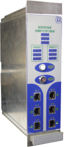
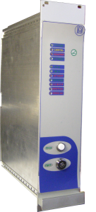
MK-SSW-CAN/ETHERNET
Safe Switcher Unit
Characteristics of the unit:
- Dual-channel safety architecture;
- As Ethernet controllers are connected, depending on the CAN - output modules, or object controllers, safety switcher compares the control commands from the first and second channel controller dependencies and, when passing control commands, switches object controllers for the backup bundle of controllers of depending;
- Perhaps the hot backup units;
- Etnernet supports 10BASE-T and 100BASE-TX;
- 2 port channel 1Mbit CAN 2.0 with galvanic isolation (they can be used as the main and backup pair);
- Display the internal state of the unit;
- Status display each bundle of depending;
- All commands go through the “AND”-hardware before heading to the CAN.
MK-OKST
Switch Controller
Characteristics of the unit:
- Control of the alone AC switch;
- Voltage - 220V three-phase AC;
- Dual-channel safety architecture;
- Measurement: The input voltage to each phase, output current of each phase, the insulation resistance;
- Control of solid-state relays with “AND”-safety at the entrance;
- Constant testing serviceability of contol keys (It's able to know change the switch'es position posibility);
- Monitoring of wire five, seven, and nine of the working circuit of a switch with three-phase motor;
- Voltage insulation tester - 300 V DC;
- Plotting current changing switch'es position;
- Unit settings are stored in external flash memory chips for each channel, before starting the configuration compared.
MK-OKS.6
Rail traffic controller
Characteristics of the unit:
- Dual-channel safety architecture;
- Control and monitoring up to 6 single-filament or double-filament lamps;
- Measurement of each channel: output voltage, output current, insulation resistance;
- Power supply line - 300V DC;
- Control of solid-state relays with “AND”-safety at the entrance;
- Lamps up to 25W;
- Voltage insulation tester - 300 V DC;
- Two-way communication between the ODFB and this MK-OKS.6;
- Via ODFB measuring input voltage, the voltage across the lamp and current through the lamp, operation filaments;
- Unit settings are stored in external flash memory chips for each channel, before starting the configuration compared.
MK-GALS.8
Code generator eight-track circuits
Characteristics of the unit:
- Switching signal 220 to 5A per channel;
- Provides generation of signals with time parameters KPT-5 and KPT-7;
- Ensuring synchronicity codes of all generators at the station and running line;
- Supply voltage - 24V DC;
- Dual-channel safety architecture;
- Perhaps the hot backup units;
- Isolation between channels and between the control electronics and the output 3000 V;
- The output of the generator is connected via a solid state relay “AND”-safety;
- Each channel measurement of the output voltage and output current;
- Indication of the parameters of the output signal on the LCD display;
- Unit settings are stored in external flash memory chips for each channel, before starting the configuration compared.
MK-GP.4
Signal generator of tonal track circuitus quad
Characteristics of the unit:
- Supply voltage - 24V DC;
- Dual-channel architecture;
- The synthesis signal on the basis of a single energy conversion efficiency of about 85%;
- For a stranger to the track circuit signal generator is a zero resistance (regardless of the frequency characteristic of the circuit solutions);
- Perhaps the hot backup units;
- Isolation between the channels and the international control electronics and access 3000 V;
- The output of the generator is connected via a solid state relay "AND"-safety;
- Each channel measurement of the output voltage and output current;
- Simulates analog load curve of the generator with a filter at running a train on a rail circuit enters the current stabilization (reducing the output voltage);
- parameter display outputs on LCD;
- Configuring the output signal with the LCD display if the resolution command from the server, and save the new settings to the external flash memory;
- Unit settings are stored in external flash memory chips for each channel, before starting the configuration compared.
MK-GARS24.2
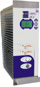
Signal Generator cruise control dual
Characteristics of the unit:
- It provides signal generation cruise control with frequencies 75-325 Hz;
- It provides two outputs voltage to 90V and output power up to 100W output;
- Supply voltage - 24V DC;
- Dual-channel safety architecture;
- The synthesis signal on the basis of a single energy conversion efficiency of about 85%;
- For a stranger to the track circuit signal generator is a zero resistance (regardless of the frequency characteristic of the circuit solutions);
- Perhaps the hot backup units;
- Isolation between channels and between the control electronics and the output 3000 V;
- The output of the generator is connected via a solid state relay “AND”-safety;
- Each channel measurement of the output voltage and output current;
- Simulates analog load curve of the generator with a filter at running a train on a rail circuit enters the current stabilization (reducing the output voltage);
- Indication of the parameters of the output signal on the LCD display;
- Configuring the output signal with the LCD display if the resolution command from the server, and save the new settings to the external flash memory;
- Unit settings are stored in external flash memory chips for each channel, before starting the configuration compared.
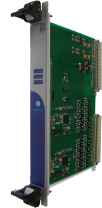
MK-PTRC.10
Receiver tonal track circuits
Characteristics of the unit:
- Dual-channel safety architecture with “AND”-hardware;
- Controls 10 track circuits;
- Information on all channels pass through safety "AND"-hardware;
- The algorithm works completely analogous to the behavior of an analog receiver, is recorded as the amplitude and depth of modulation of the input signal;
- It sends information about the input voltage, modulation depth, hardware errors;
- Unit settings are stored in external flash memory chips for each channel, before starting the configuration compared.
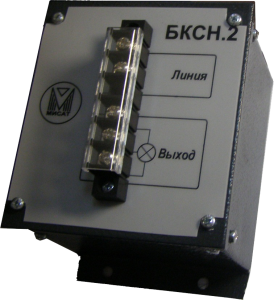
БКСН.2
Controller outdoor for double-filament bulb
Characteristics of the unit:
- The supply voltage line -100 - 300V DC or 90 - 230V AC;
- Lamps up to 25W ;
- Two-way communication between the rail traffic controller MK-OKS.6 and this one;
- Measurement of the input voltage, the voltage across the lamp and current through the lamp, operation of filaments;
- Automatic switching to the backup lamp filament;
- It can be used instead of a transformer or CT6 or CT5 with automatic detection and maintenance of the lights mode “Day” or “Night”, and switching to a serviceable filament lamps;
- Load current 10 mA at a supply voltage of 220V AC.
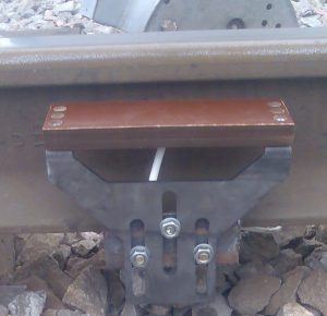
D-KZP
Track-occupancy sensor
Characteristics of the unit:
- Powered by MK-KZP;
- Sensitivity to the wheel flange of at least 45 mm;
- The measurement time three channels is 300 mcs;
- Dimensions, mm: 20x65x225;
- Standard wire length of 6 m, the maximum allowable length of 200 m;
- The weight of the D-KZP together with fastening not more than 4 kg;
- Mounting on rail R50-R75;
- Degree of protection IP67.

