Intended for:
- measuring of track circuits at the output of the filter, the input and output of the track receiver;
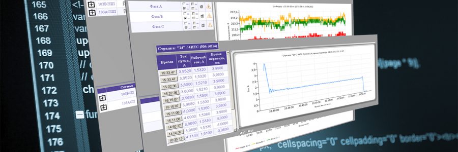
- measuring instantaneous of the voltage sample of current consumption by an switch motor, time of operation, plotting of a operation diagram;
- voltage measurements in the power feeder panels;
- recording events and storing data about the parameters of track circuits, power feeder panels and switch motors.
Consists of:
- at generator and receiver ends of track section;
- microprocessor controller of measuring parameters of AFTC (for 10 channels) MK-AITRC-10;
- at the relay -- measuring analog microprocessor controller of measuring analog signal (for 10 channels) MK-AI24-10;
- generator and receiver ends of the phase track circuits - MK-AIFCP.9;
- in the power feeder panel - MK-AI220.10;
- ITS-6 switch current meter;
- microprocessor controller of communication MK-KPI CAN/ETHERNET;
- technical diagnostics server;
- AWP maintainer.


MK-AITRC-10 is intended for measuring parameters of signals in the lines of audio frequency track circuit. It allows obtaining the effective value of the amplitude of the input modulated signal at 5 frequency bands (420 Hz, 480 Hz, 580 Hz, 720 Hz, 780 Hz) and the modulation frequency independently at each frequency band at each input.
- DC power supply voltage (9 ... 36) V;
- Maximum input voltage 115 V;
- Automatic measurement range;
- The measurement time of all channels is 1 second;
- Input impedance of at least 12 kΩ;
- Power consumption is not more than 5 W;
- Isolation between inputs up to 400V;
- The duration of the data transmission cycle (64 bits) is not more than 2 ms;
- LED indication serves to show data exchanging in the communication line, power supplying, presence of voltage at each of the inputs.
MK-AI220.10 is intended for measuring AC voltage in three-phase and single-phase circuits of power supply panels at 10 inputs.
- DC supply voltage (9 - 36) V;
- Maximum input voltage 350 V;
- All inputs are bipolar and allow you use any polarity;
- Connections can measure both consnant and it can measure both DC and AC component of the input signal;
- The measurement time of all channels is 1 second;
- Input impedance is at least 1.1 MΩ;
- Power consumption not more than 5 W;
- The duration of the data transmission cycle (64 bits) is not more than 2 ms;
- LED indication shows the presence of data exchange in the communication line, power supply, the presence of voltage at each of the inputs.


MK-AI24.10 is intended for measuring DC and AC voltages at 10 inputs (channels).
- DC supply voltage (9 - 36) V;
- Maximum input voltage 60 V;
- All inputs are bipolar and allow using for any polarity of the connection;
- It can measure both DC and AC component of the input signal;
- The measurement time of all channels is 1 second;
- Input impedance not less than 102 kΩ;
- Power consumption is not more than 5 W;
- The duration of the data transmission cycle (64 bits) is not more than 2 ms;
- Provides LED indication of the exchange of communication lines, power supply, presence of voltage on each of the inputs.
MK-AIFCP.9 is intended for measuring DC and AC voltage at 9 phase measure inputs relative to the reference signal at the 10th input.
- DC supply voltage (9 - 36) V;
- The maximum input voltage is 250 V for the reference signal input and 36 V for the other channels;
- All inputs are sensitive to correct phase wiring;
- It can measure the DC component and the AC component of the input signal;
- The measurement time of all channels is 1 second;
- Input impedance of at least 12 kΩ;
- Power consumption not more than 5 W;
- Number of inputs: 10 analog inputs;
- Communication channel with the information hub - serial asynchronous transmission data channel over a two-wire communication line;
- The duration of the data transmission cycle (64 bits) is not more than 2 ms;
- LED indication shows the presence of data exchange in the communication line, power supply, the presence of voltage at each of the inputs.

All measure controllers are made in the NMSh relay box and can be installed on standard shelves of relay racks.


Appearance ITS-6
The current meter switches ITS-6 is intended for measuring current of switch operation.
- DC supply voltage (9 - 36) V;
- Maximum measuring current - 50A;
- Galvanic isolation between measuring circuits and ITS-6;
- Number of inputs: 6 channels of galvanically current sensor for measuring DC and 3 channels (2 current sensors each) for measuring three-phase AC.
- Instantaneous current transmiting:
- for the measuring mode of direct current is 250 points per second;
- for the measuring mode of three-phase AC is 50 points per second. - Power consumption is not more than 5 W.
- The duration of the data transmission cycle (64 bits) is not more than 2 ms.
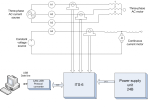 Structural diagram of a current diagnostics system for a turnout electric drive

All ITS-6 are mounted on the back side of the relay rack on DIN-rail in close proximity to the measured circuit.

The appearance of the microprocessor communication controller MK-KPI CAN/ETHERNET
MK-KPI CAN/ETHERNET is intended for converting a CAN network interface into an Ethernet network interface and vice versa and serves up to 10 clients on an Ethernet network and up to 2 independent CAN networks.
- DC supply voltage (9 - 36) V;
- Number of inputs - 2 galvanically isolated CAN ports, 1 galvanically isolated Ethernet port;
- LED indication displays the presence of the data exchange on all communication lines and the state of readiness and the failure as well;
- Packet delay is not more than 20 ms. CAN bus speed is set separately for each channel and can be up to 1Mbits / s.
- Ethernet bus speed and station mode are automatically selected by the device according to the criterion of the maximum equipment train-handling capacity and can be: 100BASE-T4, 100BASE-TX full duplex, 100BASE-TX half duplex, 10BASE-T full duplex, 10BASE-T half duplex.
All diagnostic system data are gathered and stored in the server of technical diagnostics and displayed on the AWP maintainer.

Technical Diagnostics Server

AWP maintainer

Diagram of track section signals

Diagram of the measuring power panel 1PV1-ECK1

Diagram of a Switch operation current
Functions of AWP maintainer:
- the ability to determine remotely the voltage at the output of the filter, the voltage at the input and output of the receiver of track circuits;
- the ability of Fixing values of track circuit signals which are out away from the permitted ranges;
- ability of remote determination of current consumption and operation time of electric switch motor;
- switches motor;
- ability of determining:
- voltage of feeders (I, II);
- voltage Diesel generator set;
- voltage lines supplying of switches;
- voltage lines supplying of signals;
- voltage power supply lines of track circuits;
- relay voltage poles (P, M; PT, MT; WFP, PM).
- the ability to view all (parameters, in the archive (a log of recording of events);
- print a report about change varying parameters;
- ability of a detailed view of all measuring sections at the track circuit.
Applying of the diagnostic system let you:
- Providing data collection of track circuits, switches and power supply panels;
- Determining of a pre-failure state of a track circuit and an electric switch motor;
- Performing a weekly and daily schedule for measuring the voltages on the track circuits and power supply panels;
- Fixing voltages of track circuit signals which are out away from the permitted ranges;
- Viewing records of voltage changes of individual track circuits and power supply panels;
- Viewing records of changes in current consumption and operation time of a single electric switch-motor.